Full Suspension Frame - Part 5 - Adding the main pivot and a few more layers.

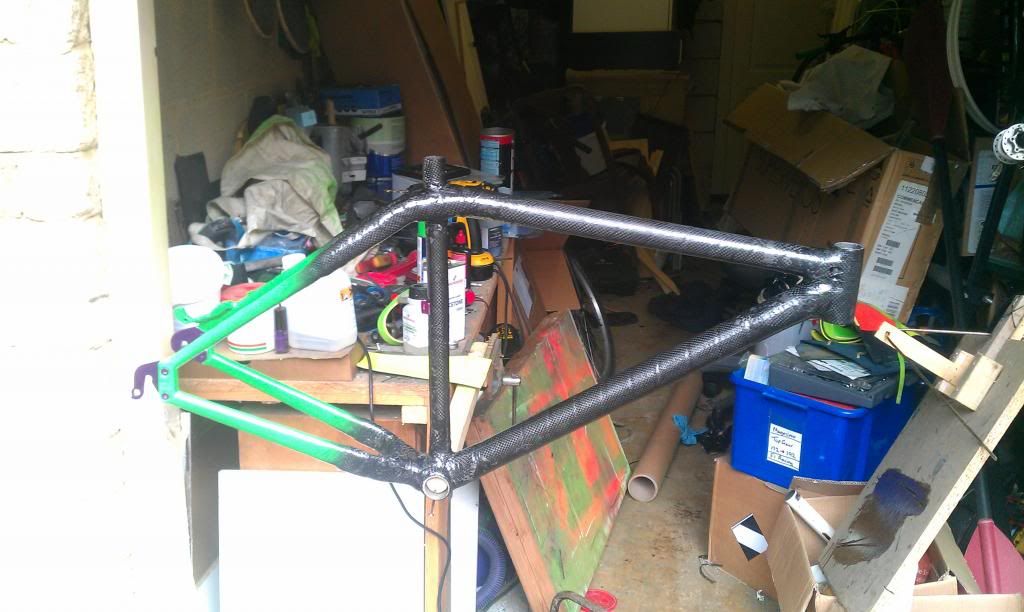
Today's building has gone well, the work I did yesterday has set nicely and the frame was able to be removed from the jig to check the alignment.


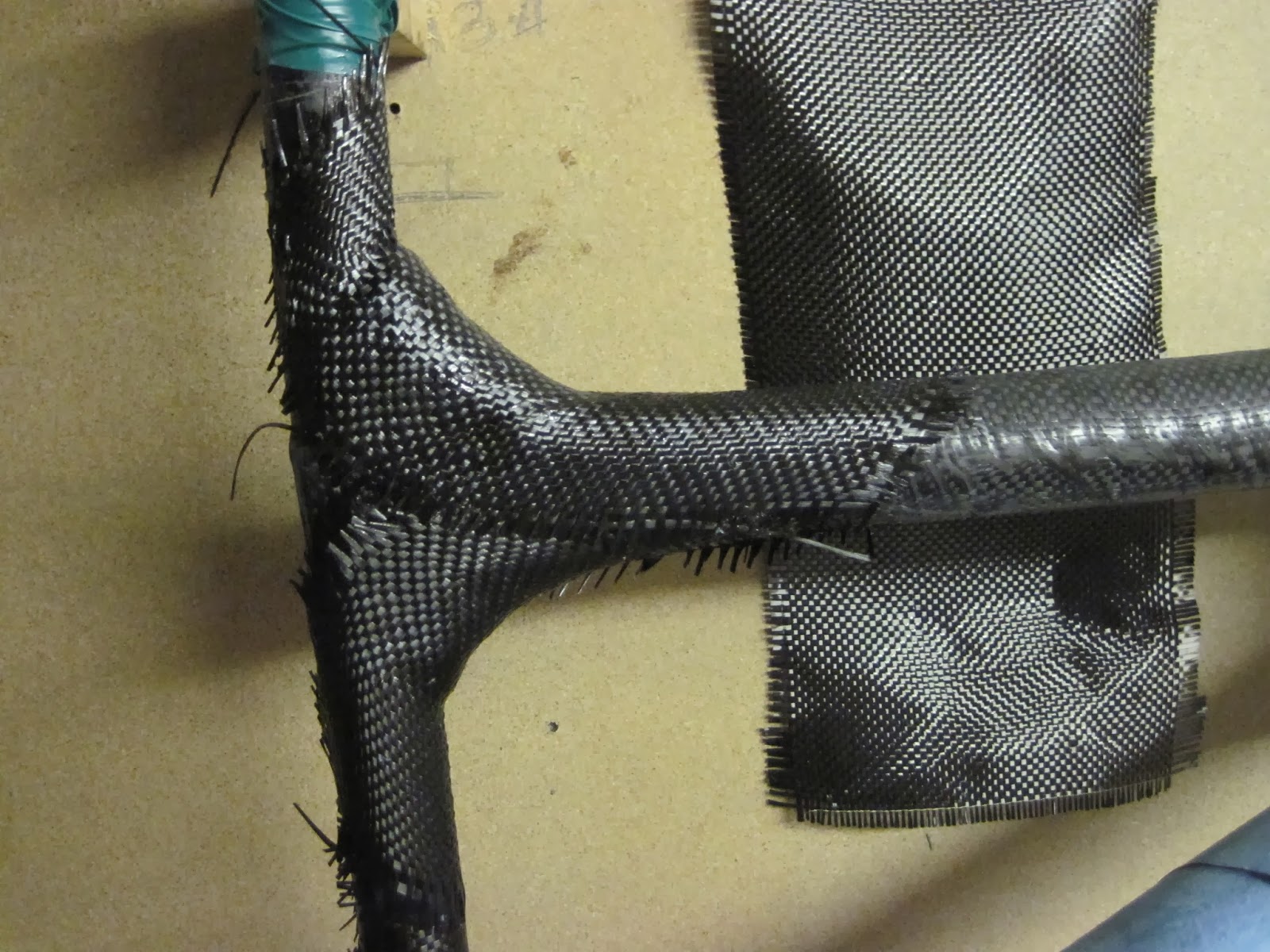
 The headtube is shown here - it is currently just held on with only 2 layers of carbon, but that is plenty to be able to remove from the jig.


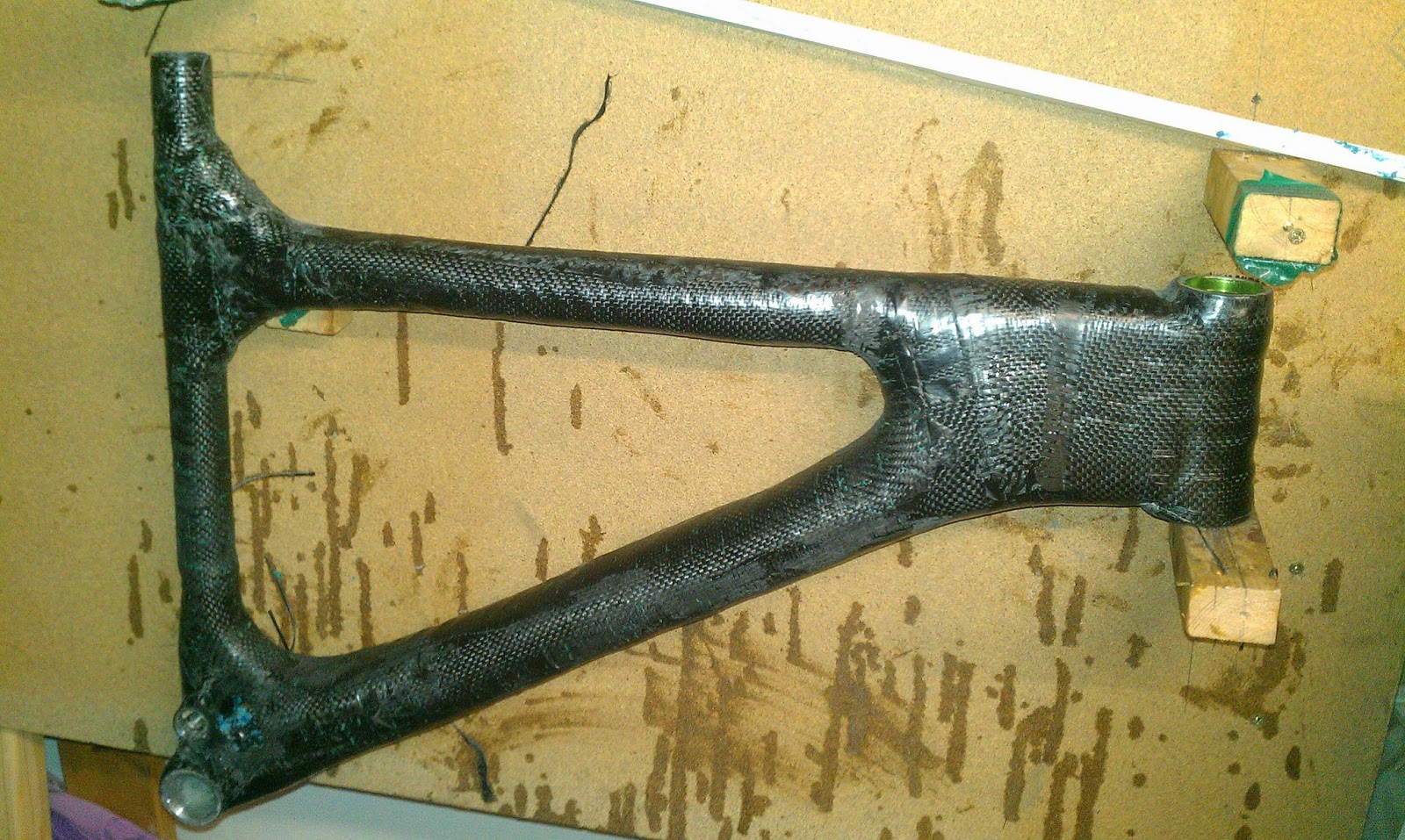
I added a jig mount for the main pivot point, it will be he in with about 5 layers of carbon as the majority of the force will be going through it.

Due to a request I have taken a few photos of the carbon lay up process - I wet the carbon cloth out on a flat sheet of wood using a foam squeegee to remove excess resin so to get the amount of resin for the best strength. I then lay the wetted cloth in position, and press it in place by hand.


All today's work is now taped up so will be setting over night, I have now got a total of 6 layers on the headtube, 3 on the seattube and 3 on the bottom bracket - will update soon with any progress!


Full Suspension Frame - Part 6 - Making the linkage and adding even more layers

The linkage I'm going to use is made out of 8*25mm aluminium, I have drilled 10mm holes in each side to remove a bit of excess weight, and I have a 5*20mm version I will try to see if I notice any difference in stiffness/strength - as that would be about 50g lighter. I intend to round the corners off and smooth the edges in the final version, but these are just the functional prototypes.

The bolts I'll be using to assemble this will be M6 stainless steel (cut to size), with nyloc nuts for extra security, I hope these will be strong enough, but I have left the scope to change to M8 if needed.

The dropouts I'll be using are off of the donor frame, they are the right shape for me to slightly enlarge the seatstay mounting holes to put the pivots in their place.

The metal inserts I'm using are 10mm steel tube for the internal sections of the pivots, 8*25mm aluminium bar for the swingarm/main pivot area and linkage, 5*20mm bar for the inserts in the shock mount, 14mm internal diameter aluminium tube for the linkage pivot and 22mm internal diameter tube for the main pivot.

Here is the next layer of tape and carbon, I have now got all the layers I intend to use on the headtube (8) and one short on both the Bottom bracket (7), and seatpost (3/4) - these will get added when I add both the suspension mounts. 

To remove excess resin I have pierced holes every 10-15mm, this should hopefully make a lighter stronger layup, and therefore frame.

Sadly these will probably be the last updates till late march as I'm now back at uni. 

Full Suspension Frame - Part 7 - jigging the swingarm

After a 2 month break I have finally been able to get going again on building the frame, looking at my previous work, it looks like I'm going to have to replace the main linkage pivot area of the frame due to a small problem with clearance of the front derailleur and the main pivot, but this shouldn't be too much of a problem as I can do it at the same time as the shock mount.


As can be seen here I have had to cut away a small area, this was due to it clashing with where the front mech will swing so I'm going have to recess it slightly


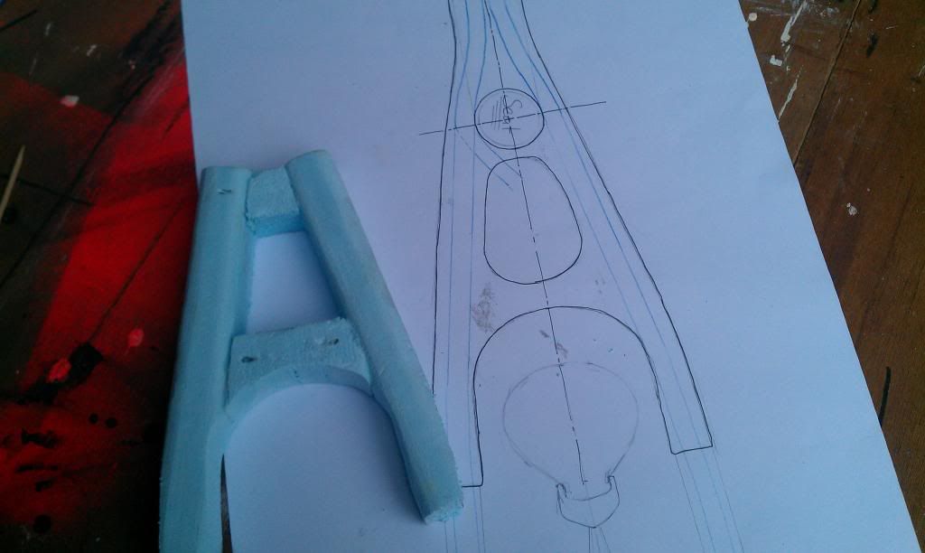
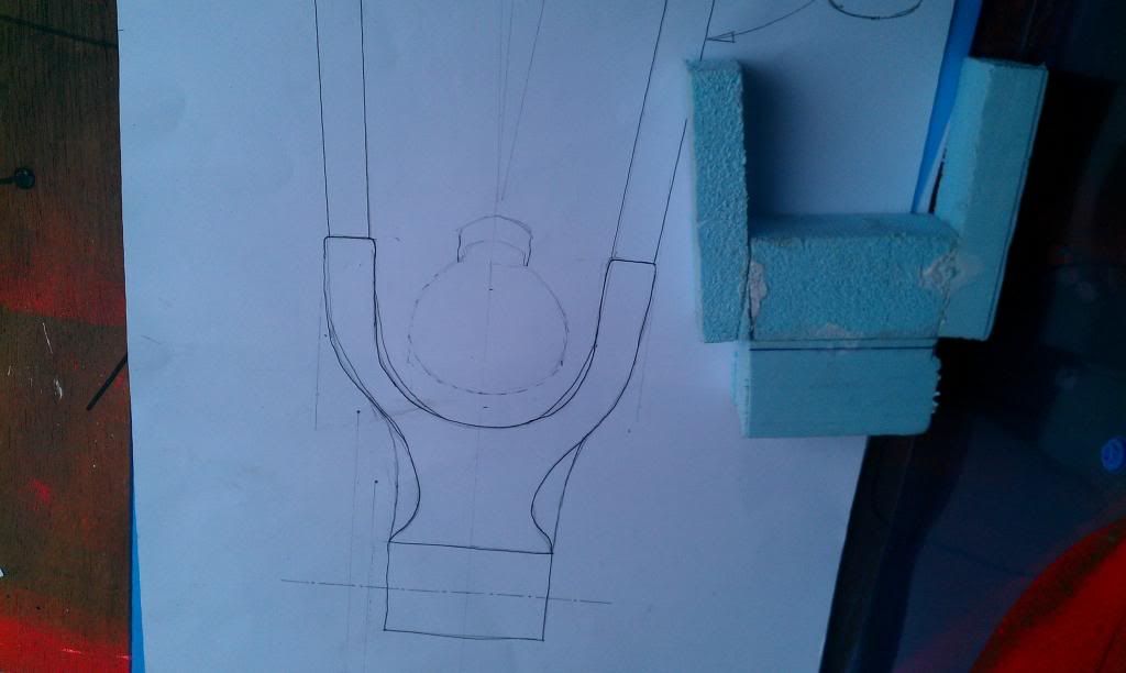
I have started to jig the foam for the swingarm, I intend to build it fully out of foam before I start to add carbon so I can perfect the geometry and make sure it doesn't contact the front triangle as it moves.


I'm hoping progress should be a bit quicker over the next week as it feels like I have got very little done over the past few days - and I'm hoping to have this done by the end of april.

Full Suspension Frame - Part 8 - Back a few steps

Today I have had to remove the main bearing mount due to having to make it about 3mm narrower due to clearance issues between the swingarm and the front mech/chainrings, I have also had to remove quite a bit of material from the non drive side to do this. Doing this was a bit of a last resort but will be necessary if I want to be able to run a double or triple chainring setup.


I have made a small amount of progress on the swingarm, I have now done the first layer of carbon around this end (with a thin layer of fibreglass to stop corrosion), so it will be ready to be attached to the chainstays by tomorrow. 


The rear shock I am going to be using initially arrived in the post today, along with a linkage from a Yeti ASR-sl, using a premade linkage will be stronger and lighter than making one myself, due to not having easy access to a milling machine, but in the future I hope to make one myself out of carbon.


Tomorrow I hope to make progress on the swingarm and hopefully the start the shock mount too.


Full Suspension Frame - Part 9 - starting to look like a bike!

The linkage is now attached and swinging freely (in the direction it's meant to!), this has allowed me to check the shock for fit and attach the shock mount to the frame. 


The mount for the linkage isn't particularly neat at the moment, but I will clean it up once I have tested that it is working well, as there is no point polishing it up incase I have to redo it. 


Here I have put the frame on it side to judge the angle for the mount, it will need to take a huge amount of force (about 2.5 times the force at the wheel) so this will have to be one of the strongest areas of the bike.


I intend to build this area up into a wedge shape to distribute the load along the top tube, but initially I have just used a small amount of resin to tack it in place.


The progress on the swingarm has been slightly slower than expected, this is mainly due to having to get the alignment right or the bike will track to one side. I also need it to be extremely stiff so I have been trying to get the layup as smooth as possible.


Full Suspension Frame - Part 10 - swingarm nearly done!

The majority of the work I did today was on the swingarm, although I did  build up a few layers around the shock mount too.


AS can be seen I have added a few layers of carbon to add strength to the shock mount, I have also used a small wedge of foam to smooth out the curve from the mount to the top tube. 


The rear swingarm is coming along nicely, as a few of you may have noticed, I have used the carbon seatstays from the donor frame as part of the swingarm, I have also made it asymetric, by having a taller stay on the non drive side, for added strength where there is no chain to interfere with it.


I have also added about 5 layers onto it so by tomorrow it should be nearly complete!


These are the aluminium inserts/pivots for the seatstays, I will bond them into the lower ends of the stays, I have had to recess the bolts so they don't foul on the brake rotor.


Full Suspension Frame - Part 11 - nearly done!

It's starting to feel like it's nearly done now, the swing arm is 95% complete, just need as quick sand down, the front triangle will be done by tomorrow and I'm making progress on the seatstays! 


As can be seen in the above photo, the swingarm is pretty much done, I'm going to neaten up the edges of the carbon on the aluminium, and sand down a few rough areas but then it's done!

 I also weighed each section of the frame, and I'm quite happy with the weight of the front triangle at 1090g, which is 10g less than target.  I'm quite disappointed with the weight of the swingarm , which weighs in at 740g - 290g over target! Because of this I may make a second lighter, full carbon swingarm should I have carbon and resin left over.


I placed it on situe with the rear triangle, by having the extremely low top tube I have slightly compromised the space for bottles, but with the right placement of the cage I will be able to fit a 750ml easily. 


The pivots I showed in the last update, but now in place on the bike, I will bond these into the ends of the tubes shown being made below.


For the seatstays I have made foam cylinders of about 12mm diameter, which I have then wrapped carbon tow around, I have aligned the majority of the fibres parallel with the length at this will need to be the direction of the strength.


AS per normal I have wrapped them in electrical tape to compress. 


I have also reattached the main pivot sleeve which I had to remove earlier, I also filled the hole in the side with foam so I could rebuild that area with carbon 


Homemade carbon xc frame - Part 3

To start the build I first made foam cores for all the complex sections such as chain-stay and seatstay bridges, which I used to mold the carbon around. For the main tubes I molded them around PVC drainage pipe using the method described here. For each section I just used 1-2 layers of carbon as the aim was just to make pieces the correct shape, as I would be adding the strength later once the pieces were assembled.

The foam cores for chainstay and seatstay bridges
After making all the individual component sections, I jigged the headtube, BB shell, seattube and dropouts into the positions they needed to be. I then used a small amount of fast set epoxy (araldite) to tack the pieces together so I could join them permanently and then build up the layers of carbon.

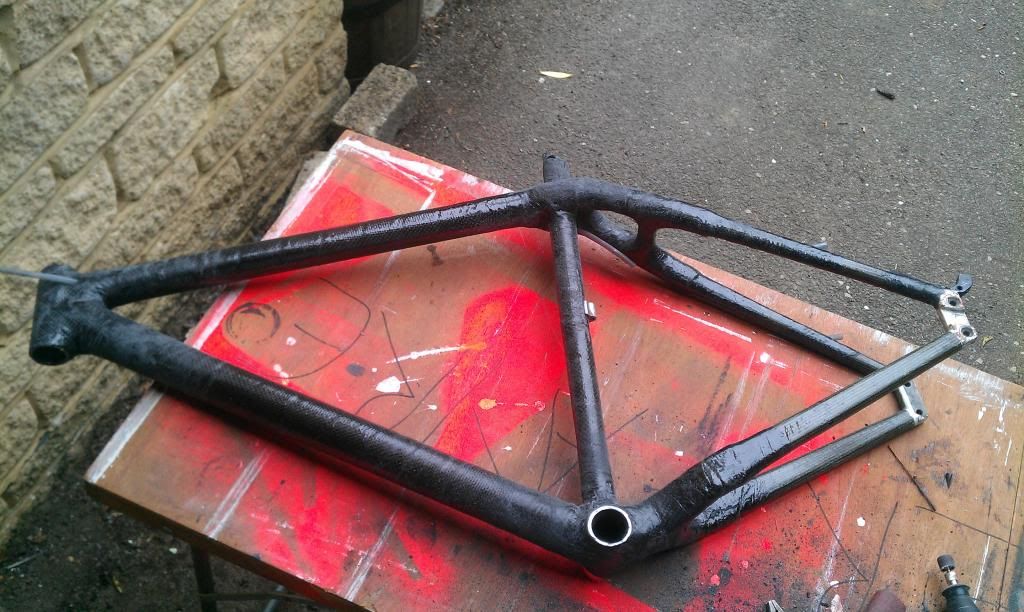
The frame with about 2-4 layers of carbon
Once the frame was fully assembled it was simply a case of adding layers of carbon, I'm not 100% sure of these numbers, but I used about 7 layers around the BB and headtube, 5 on chainstay and seatstays (and the bridges), and 4 for the center sections of the 3 main tubes.


The completed frame V1.0
Once the frame was completed I painted the rear triangle and sanded the surface to a reasonably smooth finish. I wasn't too bothered about a mirror or perfectly flat finish as I wanted to keep the garage made look!

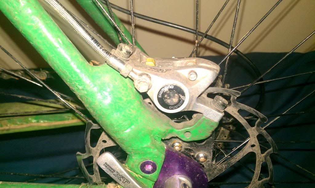
The brake mount is simply an adapter bonded in place and then a few layers of carbon for strength
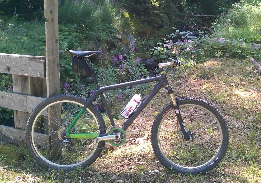
The finished bike in Austria during summer 2013
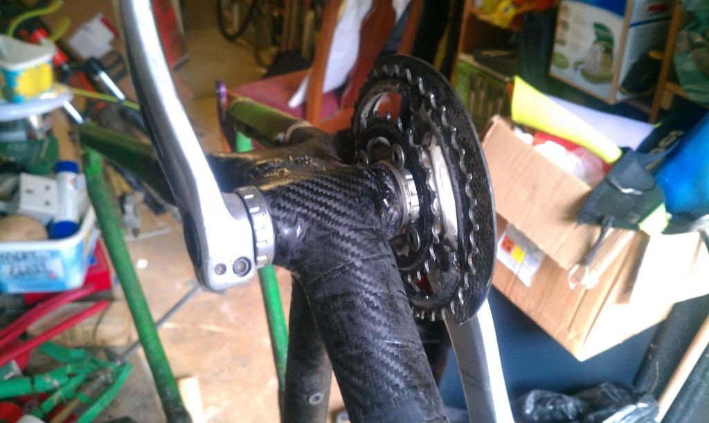
The frame has had a few teething issues, one was at Cannock Chase, where I had a hard pedal strike which dislodged the bottom bracket shell from the frame, it kept in place but had about 20 degrees of movement
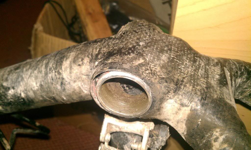
The broken BB shell
When I got home I cut the shell out to see what the cause was, and it turned out that the top half of the shell wasn't attached to anything, as it looked like the lay of carbon I had used to hold it in place had crumbled leaving it free to move should the pedals be knocked in an upward direction.

Investigative surgery 
To fix is I wrapped the shell in a few layers of carbon and the built the area up with about 4 layers. This seems to have worked as I haven't had any issues since - and I know I have had quite a few pedal strikes!

The fixed BB area - V1.1


Homemade carbon xc frame - Part 2 - buying, scrounging and lot of carbon fibre

Building a carbon fibre frame on a student budget (eg - next to nothing), was always going to be tricky, especially as carbon fibre is upwards of £21 ($35) per square meter and for a bike frame 2-3 m^2 of material is required. I was able to scrounge about 16 m^2 for a D&T project  while in school, so I had enough to spare for this, and probably a few more projects too.

             A complete list of the materials I used - all will be explained later;
                                   - Carbon sheet (approx 3m)
                                   - Epoxy resin (about 1Kg) as some goes to waste
                                   - PVC pipe for molding tubes around - clicky
                                   - Mold release wax
                                   - Blue modeling foam - various sources on eBay
                                   - Rubber tubing to make routing for internal cables 
                                   - Glass bubble filler for smoothing curves 

Unless linked the easiest and best place to get these is probably easycomposites.co.uk if you're in the UK, and elsewhere google is your friend. Research what is available as there are other methods that may be more appropriate for your project.

As for tools used I have a pretty well equipped garage, but a good supply of gloves, brushes, pots and old rags is useful for lay-up, for shaping and cutting carbon, decent waterproof sandpaper and a sharp hacksaw is advisable. 

I opted to use 32 and 40mm plastic pipe to mold the main tubes around, the 32mm would be for the top tube and the 40mm would be for the downtube, I had considered using the 50mm tubing but felt it ma have been a bit too oversized - it hindsight a larger downtube may have been a better idea to help stiffen the frame a bit

For the aluminium inserts for the headtube and bottom bracket I used the parts from the Cadex frame and for the dropouts and some of the rear triangle I decided to use part of the Cadex frame - as my aim for the initial build was to keep it simple and that it was already carbon and roughly the same cross section that I had designed.

An unmodified Giant Cadex rear dropout with an added disc mount  - retrobike.co.uk
This left me with two options for adding a rear disc mount, one would be to do something similar to the above picture, and the other would be to bond a mount onto the seatstay, which is what I decided to do.

Homemade carbon xc frame - Part 1 - planning, designing and a little bit of luck

I had been planning to make a frame of some description since doing my final year school D&T project, where I made a bamboo and carbon bike trailer, after my teacher told me a bike frame was too difficult a task to do.

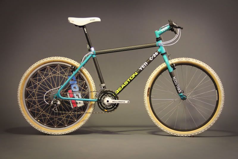
I had thought of copying the idea used by Yeti, Raleigh and a few other bike manufacturers back in the early 90's, where they bonded carbon tubes into a steel or titanium set of lugs, this idea has some major advantages, such that I could butcher an old frame and only have to make a few tubes which I could then bond into the old frame, disadvantages were that I would have to buy and destroy a perfectly good frame.
A Yeti C-26 with bonded carbon main tubes and steel rear triangle 
Another alternative would be to buy the dropouts, head-tube and BB inserts from a frame building supplier, but after looking into this it turned out that it would cost about £50 to get steel parts and upwards of £80 to get aluminium or titanium. This is where the bit of luck came in, I decided on a whim to see if anyone had any old or broken aluminium frames lying around which I could use for parts, turned out nobody did, but someone had a 1992 Giant Cadex with a cracked downtube that he was willing to sell me for £20!

A Giant Cadex - not the one I used as can't find the photos of it at the moment
This frame had the advantages that it was already partially carbon and had replaceable dropouts (gotta give SSUK champs a go), but it had a standard 1 1/8 headtube which would make future fork upgrades more difficult , as a tapered headtube had been my original plan - but for a first prototype on a budget I decided I could live with it.

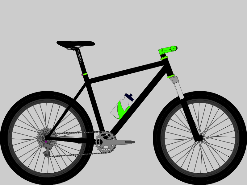
To design the frames geometry I used bikecad.ca where you can alter the geometry and tube sizes to get the desired look, shape and size. I based the geometry on my 1994 Raleigh m-trax Ti as I liked the way it handled and was the only bike that I had available to copy   

A basic mock-up of what I had aimed the bike to look like
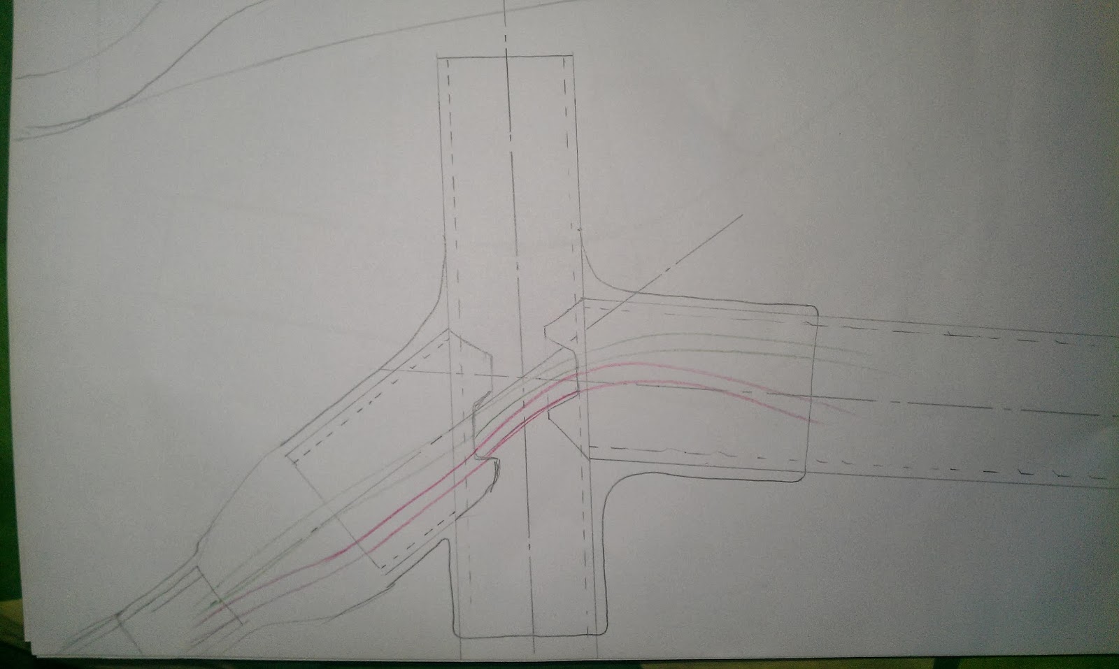
Designing more intricate parts such as the top of the seat-stays and chain-stays I used pen and paper, with help from Sheldon Browns website on clearances for chainrings and a few other sources (googled) for tyre dimensions and recommended mud clearances, this was especially important as Oxfordshire mud is particularly clingy 

The first draft designs for the chainstay (left) and seatstay (right) bridges
An early design - I had planned on a lugged carbon frame at some points

Top and side views of the seatpost/toptube/seatstay junction 
The revised design for the same area - this is a bit sleeker and easier to make
Dropout and disc mount designs 


Introduction - plans, projects and a few pictures

Following a few forum posts on singletrackworld.com detailing a few of my bike related projects and ideas for future projects and making many a promises on putting up a guide and a how to, I think I have finally managed to get a large enough collection of pictures and enough time to write the promised guides. 


The first of guide I'll try to get up will be for the above bike (or more specifically the carbon frame), where I built the frame from pretty much scratch. I'll also do a quick write up for a simple carbon bash guard, and my A-level final year project which is a bamboo and carbon bike trailer (below). 


I'll try to get the initial part of the guide for the carbon frame up by the end of next week, but for those who can't wait the initial write up I did is on singletrackworld forums - clicky